 |
All the cross products needed for measuring the four Stokes parameters (see Chapter 15) are measured in this mode. The number of channels available per baseline is again restricted to 128 and further one sideband from all 30 antennas is processed. Thus the maximum possible bandwidth in the Polar Mode is 16 MHz, as opposed to 32 MHz in the Indian Polar mode (which measures Stokes I for unpolarized sources), and the spectral resolution is also half of the maximum possible in the Indian Polar Mode.
 |
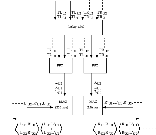
The delay-DPC multiplexer is configured so that the data
flow will be as shown in Fig 25.8. The data from one side band for
both polarizations (in this case ![]() ,
, ![]() ) is multiplexed
to get the required data sequences. The MAC is configured in the polar
mode such that it measures the cross product of the two polarizations
in addition to the cross products of a polarization with itself. Adjacent
channels of the cross product of one of the polarizations
(eg:
) is multiplexed
to get the required data sequences. The MAC is configured in the polar
mode such that it measures the cross product of the two polarizations
in addition to the cross products of a polarization with itself. Adjacent
channels of the cross product of one of the polarizations
(eg:
![]() ) are averaged and integrated in
128 accumulators of the MAC. Unlike in the Indian-Polar mode, the
second set of 128 accumulators integrate the cross product of the
two polarizations (eg:
) are averaged and integrated in
128 accumulators of the MAC. Unlike in the Indian-Polar mode, the
second set of 128 accumulators integrate the cross product of the
two polarizations (eg:
![]() ). Similar
measurements of the second polarization (i.e. in this case,
). Similar
measurements of the second polarization (i.e. in this case,
![]() and
and
![]() ) are made in
the second MAC. Thus all required cross products are measured, from
which, as described in Chapter 15 all four
Stokes parameters of the source can be computed.
) are made in
the second MAC. Thus all required cross products are measured, from
which, as described in Chapter 15 all four
Stokes parameters of the source can be computed.