The two polarized RF signals are down converted to 32 MHz or 16 MHz or 6 MHz IF band at the
antenna base centered at 70 MHz by using local oscillator (![]() LO), which is tunable in
a range of 100 MHz to 1700 MHz. The IF signals are then converted to 130 MHz and 175 MHz
using the
LO), which is tunable in
a range of 100 MHz to 1700 MHz. The IF signals are then converted to 130 MHz and 175 MHz
using the ![]() LO so that the polarization information does not intermingle with each
other. The IF signals are brought to the central receiver room via the optical fiber and
converted back to two 70 MHz bands using the
LO so that the polarization information does not intermingle with each
other. The IF signals are brought to the central receiver room via the optical fiber and
converted back to two 70 MHz bands using the ![]() LO, and provided as inputs to the
baseband system.
LO, and provided as inputs to the
baseband system.
The baseband system splits each polarization band into upper sideband and lower
sideband and down converts the signals to baseband frequency by using the ![]() LO with is
tunable in steps of 100 Hz within the range of 50 MHz to 90 MHz. Thus, by choosing the
LO with is
tunable in steps of 100 Hz within the range of 50 MHz to 90 MHz. Thus, by choosing the
![]() and
and ![]() LO, user can select the center frequency of the observing RF band. The
baseband system gives four final outputs, two sidebands for each polarization which is fed
to the correlator. (see 2.2.5).
LO, user can select the center frequency of the observing RF band. The
baseband system gives four final outputs, two sidebands for each polarization which is fed
to the correlator. (see 2.2.5).
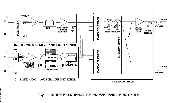
The figure (2.3) shows the block diagram of the receiver system. (Ref : Praveen Kumar, 2003)