

Next: Monitoring the health of
Up: The Data Acquisition System
Previous: Data Acquisition
Contents
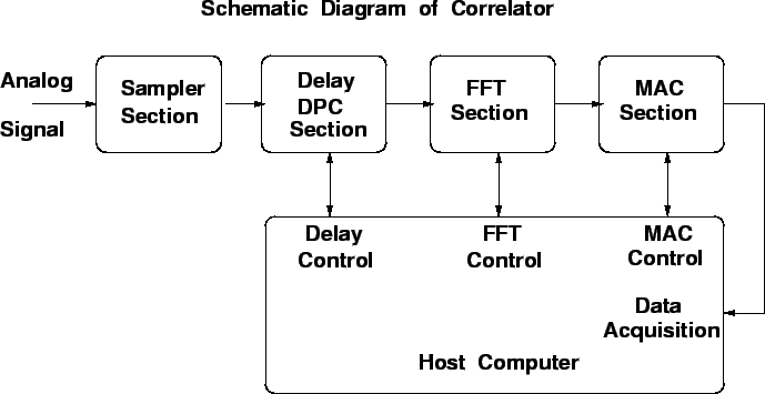
The correlator system for the GMRT serves the following four major
functions depicted in the schematic shown in the Figure 26.1.
Figure 26.1:
The schematic block diagram of the correlator. The four major
blocks of the hardware as well as the host computer are shown.
 |
- Analog to Digital Conversion.
As we mentioned earlier that the full GMRT would require
 sampling points, for thirty antennas with two side bands
in each of two polarizations. The current correlator system suffices
half of this requirement. The sampling takes place at 32 MHz in order
to have data for a maximum of 16 MHz bandwidth. There is no control
required for this unit of the correlator.
- Delay DPC unit.
Signals originating from a given point in the source, and received
via two different antennas, traverse different path lengths before
they arrive at the samplers. This different path lengths arise because
of the different locations of the two antennas as well as the different
cable lengths between the two antennas and the correlator (and are
called the geometric delay and the fixed delay respectively). As
discussed in chapter 4 the geometric delay changes with
the Hour Angle of the source. In order to compensate for the differential
delays that the signals from different streams have suffered, the Delay
unit has to be periodically updated with the current values of time
delays that have to be applied. Therefore, delay values are required to
be transmitted from the host computer down to this unit of the
correlator periodically. The Delay unit of the correlator can delay
only for the integral number of sampling time intervals, which is
1/32MHz. Finer delay corrections are made in the FFT unit, where delay
values are converted into a phase gradient across the band.
- FFT unit.
This section of the correlator carries out 512 points FFT every
 sec. The two other major tasks
that this unit performs are, 1) fringe phase subtraction, and
2) fractional sampling time delay correction (FSTC, see chapter 4).
This requires periodic updates of the phase and FSTC values that are to
be applied, which has also to be supplied by the host computer.
- MAC unit.
The MAC unit can be configured in a variety of modes. This
configuration is usually done by the host computer during the
initialization sequence.
All these units (except the samplers) need to be initialized.
The exact initialization required depends on the observing mode.
To achieve this, at the start of the observation appropriate pieces
of programs are loaded into the controllers, which then behave like
embedded systems.


Next: Monitoring the health of
Up: The Data Acquisition System
Previous: Data Acquisition
Contents
NCRA-TIFR


![]() sec. The two other major tasks
that this unit performs are, 1) fringe phase subtraction, and
2) fractional sampling time delay correction (FSTC, see chapter 4).
This requires periodic updates of the phase and FSTC values that are to
be applied, which has also to be supplied by the host computer.
sec. The two other major tasks
that this unit performs are, 1) fringe phase subtraction, and
2) fractional sampling time delay correction (FSTC, see chapter 4).
This requires periodic updates of the phase and FSTC values that are to
be applied, which has also to be supplied by the host computer.