 |
 |
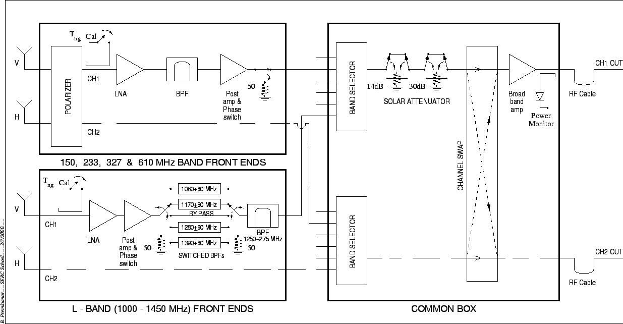
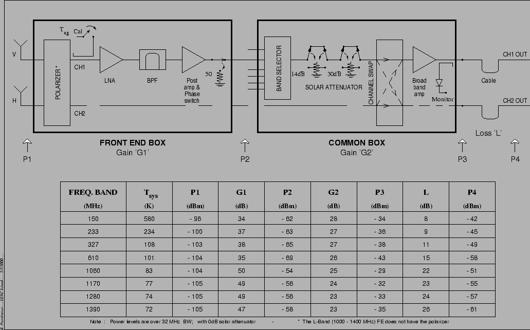
A block diagram of the Multi Frequency Front Ends is given in Figure 21.2. There are six possible observing bands centered at 50 MHz21.4, 150 MHz, 233 MHz, 327 MHz, 610 MHz and an L-band extending from 1000 to 1450 MHz21.5. The L-band is split into four sub bands centered at 1060 MHz, 1170 MHz, 1280 MHz and 1390 MHz, each with a bandwidth of 120 MHz. The L-band receiver also has a bypass mode in which the entire RF band can be brought down to the ABR.21.6 The 150 MHz, 233 MHz, 327 MHz and 610 MHz bands have a nominal bandwidth of 40 MHz21.7. Table 21.1 gives a break up of the contribution from various sources to the system noise temperatures at the different frequency bands. Figure 21.3 gives the expected RF power (for a 32 MHz bandwidth) at different stages of the multi-frequency front end.
At the lower frequencies (50 MHz to 610 MHz) there is a polarizer before the LNA which converts the received linear polarization to circular. At L band, in order to keep the system temperature low, this element is not inserted into the signal path, and the linear polarized signals are fed directly to the LNA. To calibrate the gain of the receiver chain, it is possible to inject an additional noise signal (of known strength) into the input of the LNA. It is possible to inject noise at any one of four levels. These are called Low cal, Medium cal, High cal and Extra high cal and are of monotonically increasing strength. To minimize crosstalk between different signals a phase switching facility using separate Walsh functions for each signal path is available at the RF section of the receiver. It is also possible to connect a 50 ohm resistor instead of the LNA to the output of the RF receiver. This is primarily of use in debugging.
 |
At all bands the signals go through one additional stage of amplification in the `Common Box'. The common box has a broad band amplifier which covers the entire frequency range of the GMRT. The band selector in the common box can be configured to take signals from any one of the six RF amplifiers. The common box (and the entire receiver system) has the flexibility to be configured for receiving either both polarizations at a single frequency band or a single polarization at each of two different frequency bands. It is also possible to swap the polarization channels (i.e. to make LCP come on CH2 instead of CH1 and RCP on CH1 instead of CH2), this is primarily for debugging use. For observing strong radio sources like Sun, solar attenuators of 14 dB, 30 dB or 44 dB are available in the common box. In addition there is a power monitor whose output can be continuously monitored to verify the health of the subsystems upstream of the common box.
| Band | BW | Cable Loss | Pol Loss | LNA | Receiver | Ground | Sky | Sys |
| (MHz) | (MHz) | (dB) | (dB) | (K) | (K) | (K) | (K) | (K) |
| 50 | 40 | 1.33 | 0.80 | 895 | 1651 | 19 | 6500 | 8170 |
| 150 | 40 | 0.2 | 0.75 | 150 | 260 | 12 | 308 | 580 |
| 235 | 40 | 0.55 | 0.25 | 35 | 103 | 32 | 99 | 234 |
| 327 | 40 | 0.13 | 0.18 | 30 | 55 | 13 | 40 | 108 |
| 610 | 40 | 0.22 | 0.15 | 30 | 59 | 32 | 10 | 101 |
| 1060 | 120 | 0.22 | - | 35 | 53 | 25 | 5 | 83 |
| 1170 | 120 | 0.22 | - | 32 | 49 | 24 | 4 | 77 |
| 1280 | 120 | 0.22 | - | 30 | 47 | 23 | 5 | 74 |
| 1390 | 120 | 0.22 | - | 28 | 45 | 23 | 5 | 72 |