 |
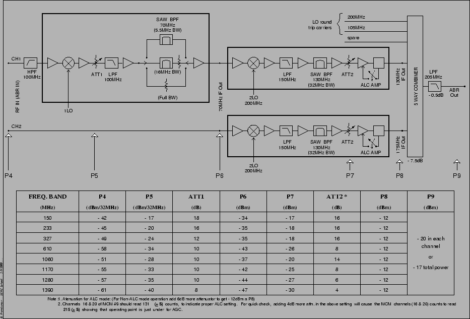
From the Common Box, the signal is brought down via a coaxial cable21.8 to the Antenna Based Receiver (ABR), which is housed in a shielded room inside the antenna shell21.9 Figure 21.4 shows a schematic block diagram (and also gives the expected signal levels for a 32 MHz bandwidth) at different stages of the ABR, and the nominal values to be set for the pre and post attenuators (see below).
 |
The High pass filter (HPF) at the input of the ABR has a
rejection of about 40 dB at 70 MHz and provides the IF
rejection21.10. After mixing
the signal power level can be adjusted using a variable
attenuator21.11 (which can be set from 0 to 30 dB in steps
of 2 dB). After this the the signal passes through a SAW filter
where one of three bandwidths (32 MHz, 16 MHz and 5.5 MHz) can
be chosen. The net gain of the filter is independent of the
chosen bandwidth due to the incorporation
of bandwidth compensating gain circuitry. The signal is then
up-converted to either 130 or 175 MHz (depending on which polarization
it is), passed through further gain and an attenuation21.12 and then an Automatic Level Controller,
(ALC). The ALC ensures that the even if the RF signal level
varies (for eg. because you point at a bright source) the signal
level at the IF remains at the optimum level for transmission
through the optical fiber21.13The IF powers are continuously monitored and the monitoring data
is sent to the CEB. The recommended IF power level is ![]() dBm per
polarization.
dBm per
polarization.
At the final stage of the ABR, the LO round trip carriers, the monitoring data as well as the astronomical signal are combined in a 5 way combiner and sent to the CEB via the optical fiber link.