next up previous contents
Next: Frequency Shift Keying Up: A Control and Monitor Previous: Error Detection   Contents


Signal Modulation

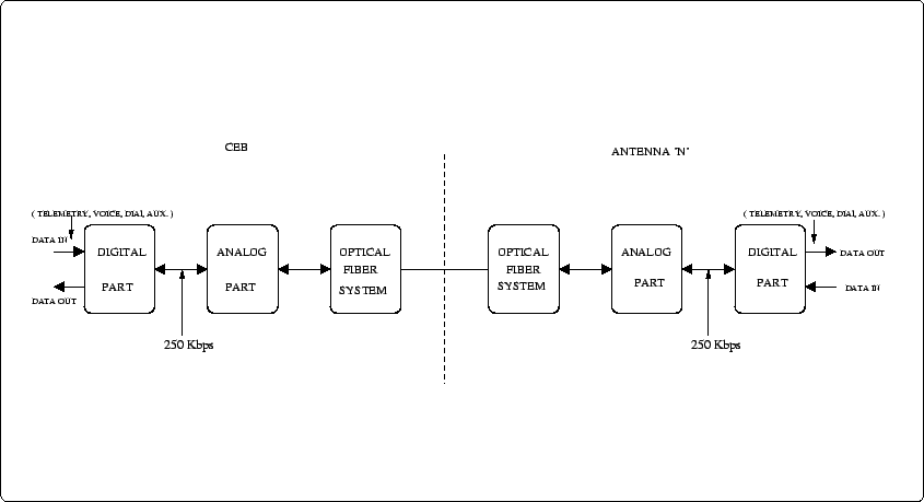
As described above, the Control and Monitor system hardware essentially consists of a digital part, an analog part and the Optical Fiber system (see Figure 24.7).

Figure 24.7: Schematic of the GMRT telemetry system. See the text for more information.
\begin{figure}\centerline{\epsfig{file=TelemetrySchematicCor.ps, width=4.4in}}
\centerline{\epsfig{file=TelemetrySchematic.ps, angle=-90,width=4in}}\end{figure}

The optical fiber is a single mode analog link operating at 1310 nm, and can carry signals from a few MHz to about 1 GHz. There are two fibers (an `forward link' and a `return link') between the Central Electronics Building (CEB) and each antenna. In the forward link the telemetry signals use an 18 MHz carrier, and the return link has a 205.5 MHz carrier. See Figure 24.8 for a schematic of the different signals carried by the forward and return links.
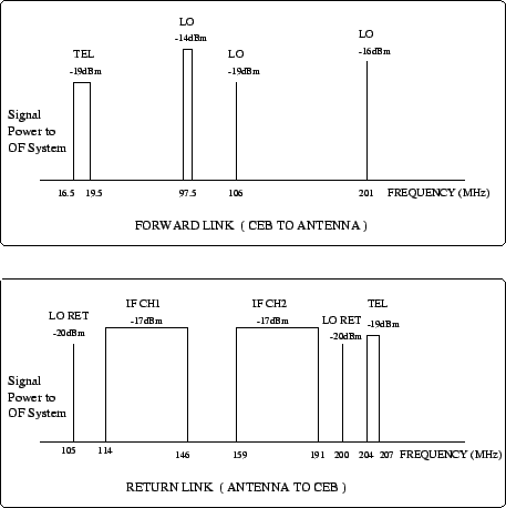
Figure 24.8: Schematic of the signals carried by the forward and return link. See the text for more information.
\begin{figure}\centerline{\epsfig{file=IFSignals.ps, width=4in}}\end{figure}


Subsections
next up previous contents
Next: Frequency Shift Keying Up: A Control and Monitor Previous: Error Detection   Contents
NCRA-TIFR