 |
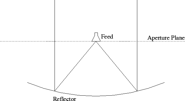
The next step is to understand how to compute the power pattern of a given telescope. Consider a parabolic reflecting telescope being fed by a feed at the focus. The radiation from the feed reflects off the telescope and is beamed off into space (Figure 3.12). If one knew the radiation pattern of the feed, then from geometric optics (i.e. simple ray tracing, see Chapter 19) one could then calculate the electric field on the plane across the mouth of the telescope (the `aperture plane'). How does the field very far away from the telescope lookslike? If the telescope surface were infinitely large, then the electric field in the aperture plane is simply a plane wave, and since a plane wave remains a plane wave on propagation through free space, the far field is simply a plane wave traveling along the axis of the reflector. The power pattern is an infinitely narrow spike, zero everywhere except along the axis. Real telescopes are however finite in size, and this results in diffraction. The rigorous solution to the diffraction problem is to find the appropriate Green's function for the geometry, this is often impossible in practise and various approximations are necessary. The most commonly used one is Kirchoff's scalar diffraction theory. However, for our purposes, it is more than sufficient to simply use Huygen's principle.
Huygen's principle states that each point in a wave front can
be regarded as an imaginary source. The wave at any other point can
then be computed by adding together the contributions from each
of these point sources. For example consider a one dimensional aperture,
of length ![]() with the electric field distribution (`aperture illumination')
with the electric field distribution (`aperture illumination')
![]() . The field at a point P(R,
. The field at a point P(R, ![]() ) (Figure 3.13) due
to a point source at a distance x from the center of the aperture is (if
) (Figure 3.13) due
to a point source at a distance x from the center of the aperture is (if
![]() is much greater than
is much greater than ![]() ) is:
) is:
Where ![]() is simply the difference in path length between
the path from the center of the aperture to the point P and the path from
point
is simply the difference in path length between
the path from the center of the aperture to the point P and the path from
point ![]() to point P. Since the wave from point
to point P. Since the wave from point ![]() has a shorter path
length, it arrives at point P at an earlier phase. The total electric
field at P is:
has a shorter path
length, it arrives at point P at an earlier phase. The total electric
field at P is:

where
The region in which the field pattern is no longer dependent on the distance
from the antenna is called the far field region.
The integral operation in equation (3.5.13) is called the
Fourier transform. ![]() is the Fourier transform of
is the Fourier transform of ![]() ,
which is often denoted as
,
which is often denoted as
![]() . The Fourier transform
has many interresting properties, some of which are listed below (see
also Section 2.5).
. The Fourier transform
has many interresting properties, some of which are listed below (see
also Section 2.5).
If
![]() and
and
![]() then
then
![]() .
.
The Fourier transform is an invertible operation; if
If
![]() then
then
![]() . This means that an antenna beam can be steered
across the sky simply by introducing the appropriate linear phase gradient
in the aperture illumination.
. This means that an antenna beam can be steered
across the sky simply by introducing the appropriate linear phase gradient
in the aperture illumination.
If
![]() , then
, then
If
![]() , then
, then
With this background we are now in a position to determine the
maximum effective aperture of a reflecting telescope. For a 2D aperture with
aperture illumination ![]() , from equation (3.4.10)
, from equation (3.4.10)
But the field pattern is just the normalized far field electric field strength, i.e.
where
![]() . From property (5)
. From property (5)
and from Parseval's theorem,
substituting in equation (3.5.14) using equations (3.5.15), 3.5.16 gives,

For uniform illumination
Note that since ![]() and
and ![]() are in units of wavelength, so is
are in units of wavelength, so is ![]() .
.
![]() however is in physical units. Uniform illumination gives the
maximum possible aperture efficiency (i.e. 1), because if the illumination
is tapered then the entire available aperture is not being used.
however is in physical units. Uniform illumination gives the
maximum possible aperture efficiency (i.e. 1), because if the illumination
is tapered then the entire available aperture is not being used.
As a concrete example, consider a 1D uniformly illuminated
aperture of length ![]() . The far field is then
. The far field is then

This is called a 1D sinc function. The 1st null is at
![]() , the
1st sidelobe is at
, the
1st sidelobe is at
![]() and is of strength
and is of strength ![]() . The
strength of the power pattern 1st sidelobe is
. The
strength of the power pattern 1st sidelobe is
![]() . This
illustrates two very general properties of Fourier transforms:
. This
illustrates two very general properties of Fourier transforms:
Figure 3.14 shows a plot of the the power and field patterns for a 700 ft, uniformly illuminated aperture at 2380 MHz.
Aperture illumination design hence involves the following following tradeoffs (see also Chapter 19):
Another important issue in aperture illumination is the amount
of aperture blockage. The feed antenna is usually suspended over the
reflecting surface (see Figure 3.3) and blocks out part of
the aperture. If the illumination is tapered, then the central part of
the aperture has the highest illumination and blocking out this region
could have a drastic effect on the power pattern. Consider again a 1D
uniformly illuminated aperture of length l with the central portion of length ![]() blocked
out. The far field of this aperture is (from the linearity of fourier
transforms) just the difference between the far field of an aperture of
length
blocked
out. The far field of this aperture is (from the linearity of fourier
transforms) just the difference between the far field of an aperture of
length ![]() and an aperture of length d, i.e.
and an aperture of length d, i.e.
The field pattern of the ``missing'' part of the aperture has a broad main
beam (since ![]() ). Subtracting this from the pattern due to the entire
aperture will give a resultant pattern with very high sidelobes.
In Figure 3.15 the solid curve is the pattern due to the
entire aperture, the dotted line is the pattern of the blocked part and
the dark curve is the resultant pattern. (This is for a 100ft blockage of a
700 ft aperture at 2380 MHz). Aperture blockage has to be minimized for a
`clean' beam, many telescopes have feeds offset from the reflecting surface
altogether to eliminate all blockage.
). Subtracting this from the pattern due to the entire
aperture will give a resultant pattern with very high sidelobes.
In Figure 3.15 the solid curve is the pattern due to the
entire aperture, the dotted line is the pattern of the blocked part and
the dark curve is the resultant pattern. (This is for a 100ft blockage of a
700 ft aperture at 2380 MHz). Aperture blockage has to be minimized for a
`clean' beam, many telescopes have feeds offset from the reflecting surface
altogether to eliminate all blockage.
As an example of what we have been discussing, consider the Ooty
Radio Telescope (ORT) shown in Figure 3.16. The reflecting surface
is a cylindrical paraboloid (
![]() ) with axis parallel to the
Earth's axis. Tracking in RA is accomplished by rotating the telescope about
this axis. Rays falling on the telescope get focused onto the a line focus,
where they are absorbed by an array of dipoles. By introducing a linear phase
shift across this dipole array, the antenna beam can be steered in
declination (the ``phase shift'' property of Fourier transforms). The reflecting
surface is only part of a paraboloid and does not include the axis of
symmetry, the feed is hence completely offset, there is no blockage. The beam
however is fan shaped, narrow in the RA direction (i.e. that conjugate to
the
) with axis parallel to the
Earth's axis. Tracking in RA is accomplished by rotating the telescope about
this axis. Rays falling on the telescope get focused onto the a line focus,
where they are absorbed by an array of dipoles. By introducing a linear phase
shift across this dipole array, the antenna beam can be steered in
declination (the ``phase shift'' property of Fourier transforms). The reflecting
surface is only part of a paraboloid and does not include the axis of
symmetry, the feed is hence completely offset, there is no blockage. The beam
however is fan shaped, narrow in the RA direction (i.e. that conjugate to
the ![]() dimension) and broad in the DEC (i.e. that conjugate to the
dimension) and broad in the DEC (i.e. that conjugate to the
![]() dimension).
dimension).
 |
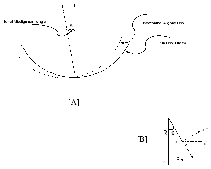
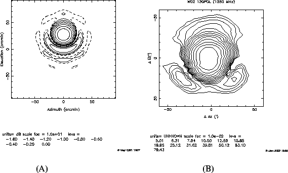
Aperture blockage is one of the reasons why an antenna's power pattern would deviate from what one would ideally expect. Another common problem that affects the power pattern is the location of the feed antenna. Ideally the feed should be placed at the focus, but for a variety of reasons, it may actually be displaced from the focus. For example, as the antenna tracks, the reflecting surface gets distorted and/or the feeds legs bend slightly, and for these reasons, the feed is displaced from the actual focal point of the reflector. In an antenna like the GMRT, there are several feeds mounted on a cubic turret at the prime focus, and the desired feed is rotated into position by a servo system (see Chapter 19). Small errors in the servo system could result in the feed pointing not exactly at the vertex of the reflector but along some slightly offset direction. This is illustrated in Figure 3.17. For ease of analysis we have assumed that the feed is held fixed and the reflector as a whole rotates. The solid line shows the desired location of the reflector (i.e. with the feed pointing at its vertex) while the dashed line shows the actual position of the reflector. This displacement between the desired and actual positions of the reflector results in an phase error (produced by the excess path length between the desired and actual reflector positions) in the aperture plane. From the geometry of Figure 3.17 this phase error can be computed, and from it the corresponding distortion in the field and power patterns can be worked out. Figure 3.18[A] shows the result of such a calculation. The principal effect is that the beam is offset slightly, but one can also see that its azimuthal symmetry is lost. Figure 3.18[B] shows the actual measured power pattern for a GMRT antenna with a turret positioning error. As can be seen, the calculated error pattern is a fairly good match to the observed one. Note that in plotting Figure 3.18[B] the offset in the power pattern has been removed (i.e. the power pattern has been measured with respect to its peak position).
 |