Signals received by antennas are down converted to baseband by
mixing with a local oscillator of frequency ![]() . The geometric delay
compensation is usually done by introducing delays in the baseband signal.
The output of a correlator after introducing a delay
. The geometric delay
compensation is usually done by introducing delays in the baseband signal.
The output of a correlator after introducing a delay ![]() can be written
as (see Chapter 4)
can be written
as (see Chapter 4)
| (9.1.2) | |||
| (9.1.3) |
where ![]() is the baseband frequency and
is the baseband frequency and
![]() is the residual delay. There are two terms
that arise in the equation due to delay compensation:
is the residual delay. There are two terms
that arise in the equation due to delay compensation:
The first term is due to finite precision of delay compensation
and the later is a consequence of the delay being compensated in the
baseband (as opposed to the RF, which is where the geometric delay is
suffered, see Chapter 4). The phase
![]() depends
on
depends
on ![]() . For observations with a bandwidth
. For observations with a bandwidth ![]() this term
produces a phase gradient across
this term
produces a phase gradient across ![]() . The phase gradient is a
function of time since the delay error changes with time. The phase
. The phase gradient is a
function of time since the delay error changes with time. The phase
![]() is independent of
is independent of ![]() , thus is a constant
across the entire band. This phase is also a function of time due to time
dependence of
, thus is a constant
across the entire band. This phase is also a function of time due to time
dependence of ![]() . Thus both these quantities have to be dynamically
compensated.
. Thus both these quantities have to be dynamically
compensated.
 |
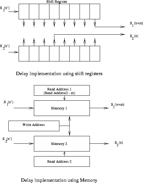
Delay compensation in multiples of sampling interval ![]() can
be achieved by shifting the sampled data (see Chapter 8). This is
schematically shown in Fig. 9.1. The digitized samples are
passed through shift registers. The length of the shift registers are
adjusted to introduce the required delay between the signals. Another
way of implementing delay is by using random access memory (RAM). In
this scheme, the data from the antennas are written into a RAM
(Fig. 9.1). The data is then read out from this memory for
further proccessing. However, the read pointer and the write pointer are
offset, and the offset between the two can be adjusted to introduce
exactly the required delay. In the GMRT correlator, the delay
compensation is done using such a high speed dual port RAM.
can
be achieved by shifting the sampled data (see Chapter 8). This is
schematically shown in Fig. 9.1. The digitized samples are
passed through shift registers. The length of the shift registers are
adjusted to introduce the required delay between the signals. Another
way of implementing delay is by using random access memory (RAM). In
this scheme, the data from the antennas are written into a RAM
(Fig. 9.1). The data is then read out from this memory for
further proccessing. However, the read pointer and the write pointer are
offset, and the offset between the two can be adjusted to introduce
exactly the required delay. In the GMRT correlator, the delay
compensation is done using such a high speed dual port RAM.
A fractional delay can be introduced by changing the phase of the sampling clock. The phase is changed such that signals from two antennas are sampled with a time difference equal to the fractional delay. A second method is to introduce phase gradients in the spectrum of the signal (see Chapter 8). This phase gradient can be introduced after taking Fourier Transforms of signals from the antennas (see Section 9.2.1).
Compensation of
![]() , (called fringe stopping,
can be done by changing the phase of the local oscillator signal by an
amount
, (called fringe stopping,
can be done by changing the phase of the local oscillator signal by an
amount ![]() so that
so that
![]() . Alternatively,
this compensation can be achieved digitally by multiplying the sampled time
series by
. Alternatively,
this compensation can be achieved digitally by multiplying the sampled time
series by
![]() . (Recall from above that the fringe rate is
the same for all frequency channels, so this correction can be done in the
time domain). The fringe
. (Recall from above that the fringe rate is
the same for all frequency channels, so this correction can be done in the
time domain). The fringe
| (9.1.4) |
| (9.1.5) |
i.e. ![]() is the phase of an oscillator with frequency
is the phase of an oscillator with frequency
| (9.1.6) |
After a time interval ![]() the frequency of the oscillator has to
be updated. Digital implementation of an oscillator of this type is called
a Number controlled oscillator (NCO). The frequency of the oscillator
is varied by loading a control
the frequency of the oscillator has to
be updated. Digital implementation of an oscillator of this type is called
a Number controlled oscillator (NCO). The frequency of the oscillator
is varied by loading a control ![]() to the device. The initial phase
of the NCO can also be controlled which is used to introduce
to the device. The initial phase
of the NCO can also be controlled which is used to introduce
![]() . In the GMRT correlator, fringe stopping is done using
an NCO.
. In the GMRT correlator, fringe stopping is done using
an NCO.