

Next: FX Correlator
Up: Correlator - II: Implementation
Previous: Delay Tracking and Fringe
Contents
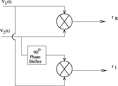
Figure 9.2:
Block diagram of a complex multiplier.
 |
The output of a simple multiplier of the two element interferometer after
delay compensation can be written as:
 |
(9.2.7) |
To separate  and
and  a second product is measured after
introducing a phase shift of
  in the signal path (see Fig 9.2).
Introducing a
  shift in the path of one of the signals will result
in (se Eq. 9.0.1)
 |
(9.2.8) |
and after compensating for 
From these two measurement we get
Alternatively, for mathematical convenience, the two measurements
can be considered as the real and imaginary part of a complex
number, i.e.
 |
(9.2.12) |
Thus the pair of multipliers together with an integrator (to get the time
average) form the basic element of a complex correlator.
In the above analysis a narrow band signal
(quasi monochromatic) is considered.
In an actual interferometer the observations are made over a finite bandwidth
 and one requires the complex visibilities to be measured as a
function of frequencies within
  . This can be achieved in one
of the two ways described below.
Subsections


Next: FX Correlator
Up: Correlator - II: Implementation
Previous: Delay Tracking and Fringe
Contents
NCRA-TIFR

![]() and one requires the complex visibilities to be measured as a
function of frequencies within
and one requires the complex visibilities to be measured as a
function of frequencies within ![]() . This can be achieved in one
of the two ways described below.
. This can be achieved in one
of the two ways described below.